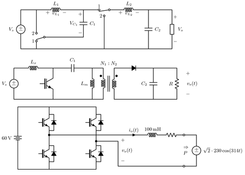
The following diagrams show diagrams related to Electrical Engineering and specifically to Power Electronics:
- A buck^2 dc-dc converter
- An isolated SEPIC dc-dc converter
- A full-bridge inverter connected to the grid through an RL filter

Edit and compile if you like:
% Power electronics---converters and inverter
% Author: Ali Mehrizi-Sani
\documentclass[landscape]{article}
\usepackage[active,tightpage]{preview}
\PreviewEnvironment{center}
\renewcommand{\PreviewBbAdjust}{0pt -10pt 100pt 0pt}
\usepackage{siunitx}
\usepackage[american,cuteinductors,smartlabels]{circuitikz}

\usetikzlibrary{calc}
\ctikzset{bipoles/thickness=1}
\ctikzset{bipoles/length=0.8cm}
\ctikzset{bipoles/diode/height=.375}
\ctikzset{bipoles/diode/width=.3}
\ctikzset{tripoles/thyristor/height=.8}
\ctikzset{tripoles/thyristor/width=1}
\ctikzset{bipoles/vsourceam/height/.initial=.7}
\ctikzset{bipoles/vsourceam/width/.initial=.7}
\tikzstyle{every node}=[font=\small]
\tikzstyle{every path}=[line width=0.8pt,line cap=round,line join=round]

\begin{document}
\begin{center}
\begin{circuitikz}
    \draw
    (0,0)
        to[V, l=$V_s$] ++(0,2.5)
        to[short] ++(1,0) coordinate (A)
        to[short] ++(0.5,0)
        to[L, l^=$L_1$, v=$v_{L_1}$] ++(1.5,0)
        to[short] ++(1,0) coordinate (B)
        to[short] ++(1,0) node[above] (C) {1}
        to[open, o-o] ++(0.65,0) coordinate (D)
        to[short] ++(0.5,0)
        to[L, l^=$L_2$, v=$v_{L_2}$] ++(1.5,0)
        to[short] ++(0.5,0) coordinate (E)
        to[short] ++(1.5,0)
        to[generic, v^=$~~V_o$] ++(0,-2.5)
        --(0,0)
    (A)                                         % Left of L1, top of switch A
        to[short] ++(0,-1.5) node[left] {2}
        to[open, o-o] ++(0,-0.5) node[left] {1}
        |- (0,0)
    (B)                                         % C1 connection starting from top
        to[C, l=$C_1$] ++(0,-1.75) coordinate (Aaux)
        -- ($(A |- Aaux) + (0.5,0)$)
        to[short, o-] ++(-0.5,-0.15)
    ($(C)!0.5!(D)$)                             % Switch B low connector
        ++(0,-0.5) node[left] {2}
        to[short, o-] ++(0,-0.1)
        |- (0,0)
    (D)                                         % Switch B blade
        to[short] ++(-0.65, -0.1)
    (E)                                         % C2 connection
        to[C, l=$C_2$] ++(0,-2.5)
    (B)                                         % Vc1
        to[open, v=$V_{C_1}~~$] (Aaux)
    ;
\end{circuitikz}

\bigskip

\begin{circuitikz}
    \draw
    (0,0)
        to[V, l=$V_s$] ++(0,2)
        to[short] ++(0.5,0)
        to[L, l^=$L_x$] ++(1.5,0)
        to[short] ++(0.5,0) coordinate (Qpos)
        to[C, l^=$C_1$] ++(2.5,0) coordinate (LMpos)
        to[L, l_=$L_m$] ++(0,-2)
    (LMpos)
        to[short] ++(0.7,0) coordinate(N1)
        to[L] ++(0,-2)
        to[short] (0,0)
    (Qpos)++(0,-2)
        to[Tnigbt] ++(0,2)
    % ------------------------ Secondary side
    (N1)++(0.7,0) coordinate (N2)
        to[D*] ++(2.5,0) coordinate (C2pos)
        to[C, l_=$C_2$] ++(0,-2)
    (C2pos)
        to[short] ++(1.5,0)
        to[R, l_=$R$] ++(0,-2)
        to[short] ($(N2)+(0,-2)$)
        to[L] (N2)
    (C2pos)++(2,0)
        to[open, v^<=$v_o(t)$] ++(0,-2)
    % ------------------------ Transformer lines
    ($(N1)!0.5!(N2)$)++(-0.05,-0.5)
        -- ++(0,-1) ++(0.1,0) -- ++(0,1)
    ($(N1)!0.5!(N2)$)++(0,0.3) node {$N_1:N_2$}
    ($(N1)+(-0.15,-0.5)$) node[circ] {}
    ($(N2)+(+0.15,-0.5)$) node[circ] {}
    ;
\end{circuitikz}

\bigskip

\begin{tikzpicture}
    \draw
    % DC sources
    (0,0)
        to[battery, l=\SI{60}{\volt}] ++(0,4) coordinate (Vcc)
    ++(2,0) coordinate (NE)

    % Switches and diodes for leg a
    ++(0,-1) node [nigbt,scale=0.8,name=igbt1] {}
    ++(0,-2) node [nigbt,scale=0.8,name=igbt4] {}
    (igbt1.E)++(0,0.1) -- ++(0.3,0) to[D*] ($(igbt1.C)+(0.3,-0.1)$)
      -- ++(-0.3,0)
    (igbt4.E)++(0,0.1) -- ++(0.3,0) to[D*] ($(igbt4.C)+(0.3,-0.1)$)
      -- ++(-0.3,0)
    % --Switch connections for leg a
    (Vcc) -| (igbt1.C)
    (igbt1.E) -- (igbt4.C)
    (igbt4.E) |- (0,0)

    % Switches and diodes for leg b
    (NE)++(3,0)
    ++(0,-1) node [nigbt,scale=0.8,name=igbt3] {}
    ++(0,-2) node [nigbt,scale=0.8,name=igbt2] {}
    (igbt3.E)++(0,0.1) -- ++(0.3,0) to[D*] ($(igbt3.C)+(0.3,-0.1)$)
      -- ++(-0.3,0)
    (igbt2.E)++(0,0.1) -- ++(0.3,0) to[D*] ($(igbt2.C)+(0.3,-0.1)$)
      -- ++(-0.3,0)
    % --Switch connections for leg b
    (Vcc) -| (igbt3.C)
    (igbt3.E) -- (igbt2.C)
    (igbt2.E) |- (0,0)

    % Inductor, grid, and the return path
    (2,2.2)
        to[short, *-, i=$i_o(t)$, current/distance=0.9] ++(6,0)
        to[L, l=\SI{100}{\milli\henry}] ++(1.2,0)
        to[R] ++(1.2,0) coordinate (Lright)
        to[short] ++(1,0)
        ++(0,-2)
        to[V, l=$\sqrt{2}\cdot 230 \cos(314t)$, mirror] ++(0,2)
        ++(0,-2)
        to[short] ++(-5,0)
        |- (5,1.8) node[circ] {}

    % P and arrow
    (Lright)++(0.2,0) to[open, o-o] ++(0,-2)
    (Lright)++(0.2,-1) node [text width=2pt] {$\Rightarrow P$}

    % v_o(t)
    (6.5,2.2) to[open, v^=$v_o(t)$] ++(0,-2)
    ;
\end{tikzpicture}

\end{center}
\end{document}
Click to download: power-electronics-converter-inverter.tex • power-electronics-converter-inverter.pdf
Open in Overleaf: power-electronics-converter-inverter.tex