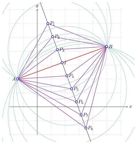
The construction of points on the perpendicular bissector of [AB]. It is achieved in an artisanal way, the purpose being to show how to achieve computations with pgf. A much simpler construction can certainly be done with other pgf commands but the idea here is to emphasize the analytical process.

Edit and compile if you like:
% Perpendicular bissector
% Author:  Hugues Vermeiren
\documentclass{minimal}
\usepackage{tikz,xifthen}

\usepackage[active,tightpage]{preview}
\PreviewEnvironment{tikzpicture}
\setlength\PreviewBorder{5pt}%


\begin{document}

\newcounter{index}
\setcounter{index}{0}

\begin{tikzpicture}[
        scale=1.0,
        MyPoints/.style={draw=blue,fill=white,thick},
        Segments/.style={draw=blue!50!red!70,thick},
        MyCircles/.style={green!50!blue!50,thin}
        ]
    % Warning : all this is an artisanal way of computing points
    % on the perpendicular bissector of [AB]
    % It could very well be achieved with more powerfull tools...
    % (package tkz-2d, for example)
    \clip (-2.5,-2.5) rectangle (7,7.5);
    \draw[color=gray,step=1.0,dotted] (-2.1,-2.1) grid (6.1,7.1);
    \draw[->] (-2,0)--(6.5,0) node[right]{$x$};
    \draw[->] (0,-2)--(0,7) node[above]{$y$};

    % Feel free to change here coordinates of points A and B
    \pgfmathparse{-sqrt(2)}		\let\Xa\pgfmathresult
    \pgfmathparse{2}		\let\Ya\pgfmathresult
    \coordinate (A) at (\Xa,\Ya);
    \pgfmathparse{5}		\let\Xb\pgfmathresult
    \pgfmathparse{13/3}		\let\Yb\pgfmathresult
    \coordinate (B) at (\Xb,\Yb);

    % Let I be the midpoint of [AB]
    \pgfmathparse{(\Xb+\Xa)/2} \let\XI\pgfmathresult
    \pgfmathparse{(\Yb+\Ya)/2} \let\YI\pgfmathresult
    \coordinate (I) at (\XI,\YI);

    \draw[red,thick] (A)--(B);

    % deltaX and deltaY are coordinates of vector AB
    \pgfmathparse{\Yb-\Ya} \let\deltaY\pgfmathresult
    \pgfmathparse{\Xb-\Xa} \let\deltaX\pgfmathresult

    % NormeddeltaX and NormeddeltaY are the normalized values of these coordinates
    \pgfmathparse{sqrt(\deltaX*\deltaX+\deltaY*\deltaY)} \let\r\pgfmathresult
    \pgfmathparse{\deltaX/\r} \let\NormeddeltaX\pgfmathresult
    \pgfmathparse{\deltaY/\r} \let\NormeddeltaY\pgfmathresult

    % R is a point on the perpendicular bissector of [AB],
    % far away from the midpoint...
    \pgfmathparse{\YI-10.0*\NormeddeltaX} \let\YR\pgfmathresult
    \pgfmathparse{\XI+10.0*\NormeddeltaY} \let\XR\pgfmathresult

    % S is the image of R by the symmetry of axis AB
    \pgfmathparse{2*\YI-\YR} \let\YS\pgfmathresult
    \pgfmathparse{2*\XI-\XR} \let\XS\pgfmathresult
    \coordinate (R) at (\XR,\YR);
    \coordinate (S) at (\XS,\YS);
    \draw (R)--(S);

    \foreach \i in {-3,-2,...,5}{
        \ifthenelse{\equal{\i}{0}}% Do not redraw the segment [AB]
            {}%
            {%
                \stepcounter{index}
                % P(i) is a variable point on the perpendicular bissector.
                % The distance between P(i) and P(i+1) is equal to 1
                \pgfmathparse{\YI-\i*\NormeddeltaX} \let\YP\pgfmathresult
                \pgfmathparse{\XI+\i*\NormeddeltaY} \let\XP\pgfmathresult
                \coordinate (P) at (\XP,\YP);
                \pgfmathparse{sqrt((\XP-\Xa)*(\XP-\Xa)+(\YP-\Ya)*(\YP-\Ya))}
                \let\radius\pgfmathresult

                \draw[MyCircles] (P) circle ({\radius});
                \draw[Segments] (P)--(A);
                \draw[Segments] (P)--(B);
                \fill[MyPoints] (P) circle (0.8mm) node[right]{$P_{\theindex}$};
            }%
        };

    \fill[MyPoints] (A) circle (0.8mm) node[left]{$A$};
    \fill[MyPoints] (B) circle (0.8mm) node[right]{$B$};
    \fill[MyPoints] (I) circle (0.8mm) node[right]{$I$};
\end{tikzpicture}

\end{document}
Click to download: perpendicular-bissector.tex • perpendicular-bissector.pdf
Open in Overleaf: perpendicular-bissector.tex