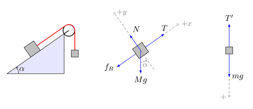
Illustration of the classical "bodies connected by a string" problem. A great advantage of using TikZ for drawing illustrations like this, is that the drawings can be parameterized. In this example the inclination angle is parameterized. PGF's mathematical engine is then used to do the necessary calculations.
Note that this example uses the shorthand scope notation in some places.

Edit and compile if you like:
\documentclass{article}
\usepackage{tikz}
\usetikzlibrary{scopes}


\begin{document}

\def\iangle{35} % Angle of the inclined plane
\def\down{-90}
\def\arcr{0.5cm} % Radius of the arc used to indicate angles

\begin{tikzpicture}[
    force/.style={>=latex,draw=blue,fill=blue},
    axis/.style={densely dashed,gray,font=\small},
    M/.style={rectangle,draw,fill=lightgray,minimum size=0.5cm,thin},
    m/.style={rectangle,draw=black,fill=lightgray,minimum size=0.3cm,thin},
    plane/.style={draw=black,fill=blue!10},
    string/.style={draw=red, thick},
    pulley/.style={thick},
]
\matrix[column sep=1cm] {
    %% Sketch
    \draw[plane] (0,-1) coordinate (base)
                     -- coordinate[pos=0.5] (mid) ++(\iangle:3) coordinate (top)
                     |- (base) -- cycle;
    \path (mid) node[M,rotate=\iangle,yshift=0.25cm] (M) {};
    \draw[pulley] (top) -- ++(\iangle:0.25) circle (0.25cm)
                   ++ (90-\iangle:0.5) coordinate (pulley);
    \draw[string] (M.east) -- ++(\iangle:1.5cm) arc (90+\iangle:0:0.25)
                  -- ++(0,-1) node[m] {};

    \draw[->] (base)++(\arcr,0) arc (0:\iangle:\arcr);
    \path (base)++(\iangle*0.5:\arcr+5pt) node {$\alpha$};
    %%
&
    %% Free body diagram of M
    \begin{scope}[rotate=\iangle]
        \node[M,transform shape] (M) {};
        % Draw axes and help lines
        {[axis,->]
            \draw (0,-1) -- (0,2) node[right] {$+y$};
            \draw (M) -- ++(2,0) node[right] {$+x$};
            % Indicate angle. The code is a bit awkward.
            \draw[solid,shorten >=0.5pt] (\down-\iangle:\arcr)
                arc(\down-\iangle:\down:\arcr);
            \node at (\down-0.5*\iangle:1.3*\arcr) {$\alpha$};
        }
        % Forces
        {[force,->]
            % Assuming that Mg = 1. The normal force will therefore be cos(alpha)
            \draw (M.center) -- ++(0,{cos(\iangle)}) node[above right] {$N$};
            \draw (M.west) -- ++(-1,0) node[left] {$f_R$};
            \draw (M.east) -- ++(1,0) node[above] {$T$};
        }
    \end{scope}
    % Draw gravity force. The code is put outside the rotated
    % scope for simplicity. No need to do any angle calculations.
    \draw[force,->] (M.center) -- ++(0,-1) node[below] {$Mg$};
    %%
&
    %%%
    % Free body diagram of m
    \node[m] (m) {};
    \draw[axis,->] (m) -- ++(0,-2) node[left] {$+$};
    {[force,->]
        \draw (m.north) -- ++(0,1) node[above] {$T'$};
        \draw (m.south) -- ++(0,-1) node[right] {$mg$};
    }
\\
};
\end{tikzpicture}

\end{document}
Click to download: free-body-diagrams.tex • free-body-diagrams.pdf
Open in Overleaf: free-body-diagrams.tex