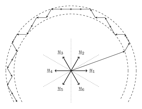
The direct torque control (DTC) method and the voltage vectors. Adapted from the figure in the handout by Jorma Luomi (2009).

Edit and compile if you like:
% The direct torque control (DTC) method and the voltage vectors.
% Adapted from the figure in the handout by Jorma Luomi (2009).
% Author: Erno Pentzin (2013)
\documentclass{article}
\usepackage{tikz}
\usepackage[active,tightpage]{preview}
\PreviewEnvironment{tikzpicture}
\setlength\PreviewBorder{10pt}%
\usetikzlibrary{decorations.markings}
\begin{document}

\begin{tikzpicture}[
	path/.style={
		->,
		>=stealth,
	},
	decoration={
		markings,
		mark=at position 0.59cm*1 with {\arrow[black]{stealth}},
		mark=at position 0.59cm*2 with {\arrow[black]{stealth}},
		mark=at position 0.59cm*3 with {\arrow[black]{stealth}},
		mark=at position 0.59cm*4 with {\draw (0,0) circle;},
		mark=at position 0.6cm*5-0.01cm with {\arrow[black]{stealth}},
		mark=at position 6mm*6-0.1 with {\arrow[black]{stealth}},
		mark=at position 7*6mm-0.1 with {\arrow[black]{stealth}},
		mark=at position 8*6mm-0.1 with {\draw (0,0) circle;},
		mark=at position 9*6mm-0.1 with {\draw (0,0) circle;},
		mark=at position 10*6mm-0.1 with {\draw (0,0) circle;},
		mark=at position 11*6mm-0.1 with {\arrow[black]{stealth}},
		mark=at position 12*6mm-0.1 with {\arrow[black]{stealth}},
		mark=at position 13*6mm-0.1 with {\arrow[black]{stealth}},
		mark=at position 14*6mm-0.1 with {\draw (0,0) circle;},
		mark=at position 15*6mm-0.1 with {\arrow[black]{stealth}},
		mark=at position 16*6mm-0.1 with {\arrow[black]{stealth}},
		mark=at position 17*6mm-0.1 with {\arrow[black]{stealth}},
		mark=at position 18*6mm-0.1 with {\arrow[black]{stealth}},
		mark=at position 19*6mm-0.1 with {\draw (0,0) circle;},
		mark=at position 20*6mm-0.1 with {\arrow[black]{stealth}},
		mark=at position 21*6mm-0.1 with {\arrow[black]{stealth}},
		mark=at position 22*6mm-0.1 with {\arrow[black]{stealth}},
		mark=at position 23*6mm-0.1 with {\draw (0,0) circle;},
	},
	radius=1pt,
]

% outer circle
\draw[dashed] (4,0) arc (0:180:4);
\draw[dashed] (4,0) arc (0:-30:4);
\draw[dashed] (-4,0) arc (180:210:4);

% inner circle
\draw[dashed] (3.5,0) arc (0:180:3.5);
\draw[dashed] (3.5,0) arc (0:-30:3.5);
\draw[dashed] (-3.5,0) arc (180:210:4);

% voltage vectors
\foreach \x in {0,60,120,180,240,300}
	\draw[->,thick] (0,0) to (\x:1);

% labels
\foreach \x/\xtext in {0/1,60/2,120/3,180/4,240/5,300/6}
	\draw (\x:1.3) node {$\underline{u}_\xtext$};

% sector dividers
\foreach \x in {30,90,150,210,270,330}
	\draw[dotted] (0,0) -- (\x:2);

% path of the stator flux
\draw[path] (0,0) -- (20:3.5); % initial flux
\draw[path,postaction=decorate] (20:3.5) -- ++(60:0.6) --
	++(120:0.6) -- ++(180:0.6) -- ++(120:0.6*2) --
	++(180:0.6) -- ++(120:0.6) -- ++(180:0.6*4) --
	++(240:0.6) -- ++(180:0.6) -- ++(240:0.6*2) --
	++(180:0.6) -- ++(240:0.6) -- ++(300:0.6) --
	++(240:0.6*2) -- ++(300:0.6) -- ++(240:0.6) --
	++(300:0.6*2);
\end{tikzpicture}

\end{document}
Click to download: ac-drive-dtc.tex • ac-drive-dtc.pdf
Open in Overleaf: ac-drive-dtc.tex